Astroimages allmost always have a background gradient that needs to be removed. Gradients can have two basic causes; either they are due to limitations of the optical system (vignetting), or to uneven illumination of the night sky. Most of us live and photograph in light polluted environments, and our astroimages incorporate stray light from street lamps or city lights. Even when photographing from a dark site, there is the inevitable sky glow. Whatever the cause of an uneven background, it is seldom something we want incorporated in our images.
PixInsight has two processes for gradient removal; Automatic Background Extraction (ABE) and Dynamic Background Extraction (DBE). These two processes work slightly different from each other, so it is a good thing to know them both. ABE is an automatic process, that does most of the work for you, especially the more laborious part of placing samples in the image. DBE on the other hand, allows for more user control.
In this article, I intend to give my experience of the DBE process, and how I use the various settings in the DBE control window.
Shortly, what you do with DBE is take samples of the background in your image and create a model of the image background, based on those samples. (Note that I assume you are working with an RGB colour image.)
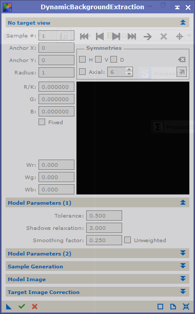 |
| Dynamic Background Extraction |
When you open the DBE process (Process | BackgroundModelization | DynamicBackgroundExtraction), you start with connecting it to an image, the target, in your workspace. This is done by either clicking in the image you wish to connect to, or clicking the reset icon at the bottom right of the control window (the four arrows pointing inwards). The latter option will also reset all settings in the control window. The active image is now linked to the process and it shows the symmetry lines that can be used by DBE. More on the symmetry lines in a moment.
Target View
Each time you click in the target window, a new sample will be created at that position. In the target view you will see how individual pixel values will be used in the creation of the background model. Each sample has a position (anchor x, y) and a size (radius). The square field in the target view panel shows how each pixel is used in the model. This field should ideally consist of only bright pixels. If the pixels have a colour, than the pixel will only be used in the calculation of the model for that colour. The three values Wr, Wg, Wb are the weights in red, green and blue for the combined pixels in the sample. They determine how much this sample will contribute to the background model. In this view you can also determine if symmetries are to be used. If you have an image which you know has a symmetrical background (vignetting for example), then you can create samples in one place where the background is visible, and use those samples in other parts of the image, even if the background there is not visible. When you click on one of the boxes (H for horizontal, V for vertical, D for diametrical), a line will show where the sample will be used. Not that you can control the symmetry for each individual sample. Use with care.
Model Parameters
In this panel you will set how strict your model is going to be. The most important value is Tolerance. Increase this if you find that too many samples are rejected. The default is 0.5, but expect to use values up to 2.5 regularly, and in extreme cases even higher than 5 - 7. But try to keep this value as low as possible. Once you have created all your samples, and are satisfied with where you placed them, you can decrease this value somewhat and recalculate the samples, until samples are being rejected. Choose the lowest value you can get away with, as this will result in a better approximation of the true background.
Smoothing factor determines how smooth your model is going to be. If you set this to 0.0 then the background will follow your samples very strictly. Increase this value to get a smoother background model if you see artefacts in the model.
Sample Generation
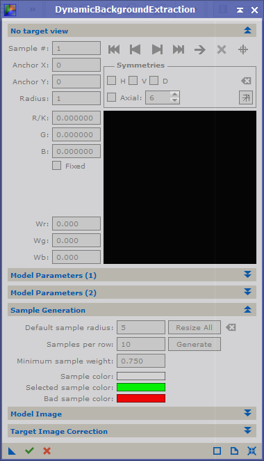 |
| DBE Sample Generation |
DBE lets you create your own samples, which is great if you have an image with lots of stars or nebulosity, but it can also create samples for you.
The first parameter sets the size of the samples. The samples will be squares with "sample size" number of pixels on either side. Use the largest samples that will not cover any stars. Obviously, if you have an image of the milky way, you will need to keep this value small, or you won't be able to position samples without covering stars.
Number of samples determines the number of samples that will be created across the image. It is generally best to use more samples. If you use to few samples, your background model may not represent your true background. Even if you have a linear background, you can model it with many samples. On the other hand, if you have a more complicated background, you can't model it with say three samples.
Minimum sample weight is only important if you let the process create samples. If you know that you have a strong gradient in the background, you should decrease its value to maybe 0.5 in order to create more samples. This parameter is used with Tolerance, to create samples in areas with more gradient.
Model Image
This is where you can set how your model background will be represented as an image. This is probably the least important panel. No comments on this panel.
Target Image Correction
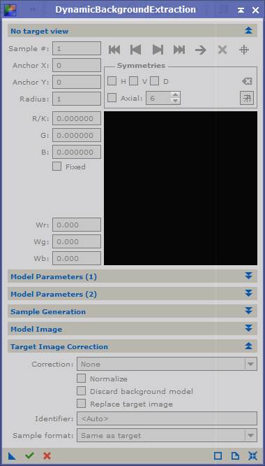 |
| DBE Target Correction |
This is probably the most important panel, as it is here you determine which type of gradient you want to remove. There are three options for gradient removal; none, which you would use to test settings without applying the process to your image; subtraction, which is used to remove gradients from light pollution or sky light; and division, which is used to remove gradients caused by the optical system.
Examine your image and determine the most likely cause of the gradients. If you find that you have gradients due to both vignetting and light pollution, you may have to apply the DBE process twice, but in many cases once is enough. If you need to apply DBE twice, it seems most logical to get rid of vignetting first, since it has affected all light entering your imaging setup. You would then first apply division as your correction method, and secondly apply subtraction with a new DBE process.
You can choose to view your background model, or to discard it. I always leave this option unchecked, since I want to examine my model. This is handy in case you want to refine your samples and settings. If you find that the model looks complicated, blotchy and with several colours, then you are probably overcorrecting. This may result in the loss of colour in nebulas. Make it a habit to check the background model before you discard it.
You can also choose to replace your image with the corrected version, or to create a new image. If you choose to create a new image, then that will not have any history. On the other hand, if you replace your original image, you keep its entire history. This can be handy.
How stars are handled in DBE
(This is the way I understand it works, which may be wrong)
If you place a sample over a star, you will notice that the sample will show a hole (= black) at the star position, with probably a colours band around this hole. This means that the pixels that represent the star, have a weight = 0, and will not be considered in the background model. However, the coloured band can be a halo or chromatic abberation, and the pixels will be taken into account for the background model. To avoid this, it is always better not to place samples over stars. If you can't avoid this, then at least examine the sample carefully, and try to place it such that it's effect is minimized. Also note that since the position of the star is not taken into account, the sample consists of fewer pixels, and each pixel will have a larger contribution for the background model.
On the size and number of samples
The samples you create should represent true background. If your image has large patches of background, you can have larger samples. If on the other hand, your image has lots of nebulosity or lots of small stars, then the background will only truly be covered by small samples. Examine your image and set sample size accordingly.
Should you use few or many samples?
It seems that some people like to use few samples in an image, while others use smaller but many samples.
There is a danger that if you use many samples, some will cover nebulosity. When the correction is applied, this will lead to destruction of the target.
On the other hand, if you only place a few samples, these may not pick up the variation of the background properly.
As usual, the number of samples that you should use must depend on the image.
Theoretically, if you have a linear gradient in an image, creating just two samples would be enough to model the background. But any mistake in either of the samples will have a severe effect on the accuracy of the background model. If you use a larger amount of samples, then each individual sample will have less effect on the background model. This generally results in a better model than using just a few samples.
I have had success with using a large number of samples (20 - 25 per row, or some 400+ samples) in my images. It does however, take quite a while to place all these samples. Even if I automatically generate the samples, I still have to make sure that they don't cover stars or part of my target.
One method that I have found helpfull is to create a clone of the image that is then stretched. This allows me to see where samples can be placed, and where they should be avoided. I then place the samples on this clone, but do not apply the correction.
After placing the samples, I create a process instance on the workspace and delete the open instance. I then apply the process on the unstretched original image.
What to look for after background extraction
As I already mentioned, I always keep the extracted background image. I examine this, and if I find that the background contains traces from nebulosity, I generally undo the extraction and change the samples in my image.
I also examine the corrected image for artefacts. If samples are too close to a target or a star, there is a chance that DBE creates a dark region around this target or star. Even in this case I undo the operation and move or remove samples.
I repeat this process until there are no dark patches left where they shouldn't be, and the background looks smooth while nebulosity has been preserved.
It can take quite a while to get the extraction right, but it will make further processing easier if you spend more time on this step.


